Product Description
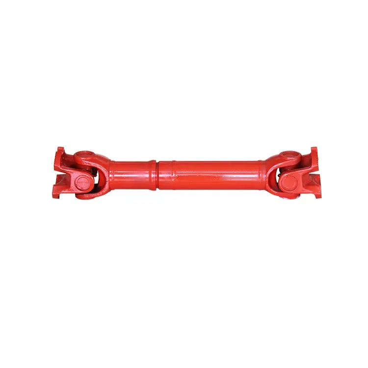
Our company has focused on cardan shafts of Papermaking equipments for almost 10 years, we can also be customized according to customer requirements. High precision and flexible joints, long service life, perfect after-sales service and so on are our highlight features.
The following table for SWC Medium-sized Universal Shaft Parameters.
Designs
Data and Sizes of SWCZ Series Universal Joint Couplings
| Type | Design Data Item |
SWC160 | SWC180 | SWC200 | SWC225 | SWC250 | SWC265 | SWC285 | SWC315 | SWC350 | SWC390 | SWC440 | SWC490 | SWC550 | SWC620 |
| A | L | 740 | 800 | 900 | 1000 | 1060 | 1120 | 1270 | 1390 | 1520 | 1530 | 1690 | 1850 | 2060 | 2280 |
| LV | 100 | 100 | 120 | 140 | 140 | 140 | 140 | 140 | 150 | 170 | 190 | 190 | 240 | 250 | |
| M(kg) | 65 | 83 | 115 | 152 | 219 | 260 | 311 | 432 | 610 | 804 | 1122 | 1468 | 2154 | 2830 | |
| B | L | 480 | 530 | 590 | 640 | 730 | 790 | 840 | 930 | 100 | 1571 | 1130 | 1340 | 1400 | 1520 |
| M(kg) | 44 | 60 | 85 | 110 | 160 | 180 | 226 | 320 | 440 | 590 | 820 | 1090 | 1560 | 2100 | |
| C | L | 380 | 420 | 480 | 500 | 560 | 600 | 640 | 720 | 782 | 860 | 1040 | 1080 | 1220 | 1360 |
| M(kg) | 35 | 48 | 66 | 90 | 130 | 160 | 189 | 270 | 355 | 510 | 780 | 970 | 1330 | 1865 | |
| D | L | 520 | 580 | 620 | 690 | 760 | 810 | 860 | 970 | 1030 | 1120 | 1230 | 1360 | 1550 | 1720 |
| M(kg) | 48 | 65 | 90 | 120 | 173 | 220 | 250 | 355 | 485 | 665 | 920 | 1240 | 1765 | 2390 | |
| E | L | 800 | 850 | 940 | 1050 | 1120 | 1180 | 1320 | 1440 | 1550 | 1710 | 1880 | 2050 | 2310 | 2540 |
| LV | 100 | 100 | 120 | 140 | 140 | 140 | 140 | 140 | 150 | 170 | 190 | 190 | 240 | 250 | |
| M(kg) | 70 | 92 | 126 | 165 | 238 | 280 | 340 | 472 | 660 | 886 | 1230 | 1625 | 2368 | 3135 | |
| Tn(kN·m) | 16 | 22.4 | 31.5 | 40 | 63 | 80 | 90 | 125 | 180 | 250 | 355 | 500 | 710 | 1000 | |
| TF(kN·m) | 8 | 11.2 | 16 | 20 | 31.5 | 40 | 45 | 63 | 90 | 125 | 180 | 250 | 355 | 500 | |
| Β(°) | 15 | 15 | 15 | 15 | 15 | 15 | 15 | 15 | 15 | 15 | 15 | 15 | 15 | 15 | |
| D | 160 | 180 | 200 | 225 | 250 | 265 | 285 | 315 | 350 | 390 | 440 | 490 | 550 | 620 | |
| Df | 160 | 180 | 200 | 225 | 250 | 265 | 285 | 315 | 350 | 3690 | 440 | 490 | 550 | 620 | |
| D1 | 137 | 155 | 170 | 196 | 218 | 233 | 245 | 280 | 310 | 345 | 390 | 435 | 492 | 555 | |
| D2(H9) | 100 | 105 | 120 | 135 | 150 | 160 | 170 | 185 | 210 | 235 | 255 | 275 | 320 | 380 | |
| D3 | 108 | 114 | 140 | 159 | 168 | 180 | 194 | 219 | 245 | 273 | 299 | 325 | 402 | 426 | |
| Lm | 95 | 105 | 110 | 125 | 140 | 150 | 160 | 180 | 195 | 215 | 260 | 270 | 305 | 340 | |
| K | 16 | 17 | 18 | 20 | 25 | 25 | 27 | 32 | 35 | 40 | 42 | 47 | 50 | 55 | |
| T | 4 | 5 | 5 | 5 | 6 | 6 | 7 | 8 | 8 | 8 | 10 | 12 | 12 | 12 | |
| N | 8 | 8 | 8 | 8 | 8 | 8 | 8 | 10 | 10 | 10 | 16 | 16 | 16 | 16 | |
| D | 15 | 17 | 17 | 17 | 19 | 19 | 21 | 23 | 23 | 25 | 28 | 31 | 31 | 38 | |
| B | 20 | 24 | 32 | 32 | 40 | 40 | 40 | 40 | 50 | 70 | 80 | 90 | 100 | 100 | |
| G | 6.0 | 7.0 | 9.0 | 9.0 | 12.5 | 12.5 | 12.5 | 15.0 | 16.0 | 18.0 | 20.0 | 22.5 | 22.5 | 25 | |
| MI(Kg) | 2.57 | 3 | 3.85 | 3.85 | 5.17 | 6 | 6.75 | 8.25 | 10.6 | 13 | 18.50 | 23.75 | 29.12 | 38.08 | |
| Size | M14 | M16 | M16 | M16 | M18 | M18 | M20 | M22 | M22 | M24 | M27 | M30 | M30 | M36 | |
| Tightening torque(Nm) | 180 | 270 | 270 | 270 | 372 | 372 | 526 | 710 | 710 | 906 | 1340 | 1820 | 1820 | 3170 |
1. Notations:
L=Standard length, or compressed length for designs with length compensation;
LV=Length compensation;
M=Weight;
Tn=Nominal torque(Yield torque 50% over Tn);
TF=Fatigue torque, I. E. Permissible torque as determined according to the fatigue strength
Under reversing loads;
β=Maximum deflection angle;
MI=weight per 100mm tube
2. Millimeters are used as measurement units except where noted;
3. Please consult us for customizations regarding length, length compensation and
Flange connections.
Brief Introduction
Processing flow
Applications
Quality Control
| Material: | Alloy Steel |
|---|---|
| Load: | Drive Shaft |
| Stiffness & Flexibility: | Stiffness / Rigid Axle |
| Journal Diameter Dimensional Accuracy: | IT6-IT9 |
| Axis Shape: | Straight Shaft |
| Shaft Shape: | Hollow Axis |
| Customization: |
Available
| Customized Request |
|---|
How do cardan shafts ensure efficient power transfer while maintaining balance?
Cardan shafts are designed to ensure efficient power transfer while maintaining balance between the driving and driven components. They employ various mechanisms and features that contribute to both aspects. Let’s explore how cardan shafts achieve efficient power transfer and balance:
1. Universal Joints:
– Cardan shafts utilize universal joints, also known as U-joints, to transmit torque from the driving component to the driven component. Universal joints consist of a cross-shaped yoke with needle bearings at each end. These needle bearings allow the joints to pivot and accommodate angular misalignment between the driving and driven components. By allowing for flexibility in movement, universal joints ensure efficient power transfer even when the components are not perfectly aligned, minimizing energy losses and maintaining balance.
2. Misalignment Compensation:
– Cardan shafts are designed to compensate for misalignment between the driving and driven components. The universal joints, along with slip yokes and telescopic sections, allow the shaft to adjust its length and accommodate variations in alignment. This misalignment compensation capability ensures that the cardan shaft can transmit power smoothly and efficiently, reducing stress on the components and maintaining balance during operation.
3. Balanced Design:
– Cardan shafts are engineered with a balanced design to minimize vibration and maintain smooth operation. The shaft tubes are typically symmetrically constructed, and the universal joints are positioned to distribute the mass evenly. This balanced design helps to reduce vibration and minimize the occurrence of unbalanced forces that can negatively impact power transfer and overall system performance. By maintaining balance, cardan shafts contribute to efficient power transmission and improve the lifespan of the components involved.
4. High-Quality Materials and Manufacturing:
– The materials used in the construction of cardan shafts, such as steel or aluminum alloy, are carefully selected for their strength, durability, and ability to maintain balance. High-quality materials ensure that the shafts can withstand the torque and operational stresses without deformation or failure, promoting efficient power transfer. Additionally, precise manufacturing processes and quality control measures are employed to ensure that the cardan shafts are accurately balanced during production, further enhancing their efficiency and balance.
5. Regular Maintenance and Inspection:
– To ensure continued efficient power transfer and balance, regular maintenance and inspection of cardan shafts are essential. This includes periodic lubrication of the universal joints, checking for wear or damage, and addressing any misalignment issues. Regular maintenance helps to preserve the balance of the shaft and ensures optimal performance and longevity.
Overall, cardan shafts ensure efficient power transfer while maintaining balance through the use of universal joints for torque transmission, misalignment compensation mechanisms, balanced design, high-quality materials, and regular maintenance. By incorporating these features, cardan shafts contribute to the smooth operation, reliability, and longevity of various applications in automotive, industrial, and other sectors that rely on efficient power transmission.

How do cardan shafts handle variations in load, speed, and misalignment during operation?
Cardan shafts are designed to handle variations in load, speed, and misalignment during operation. They incorporate specific features and mechanisms to accommodate these factors and ensure efficient power transmission. Let’s explore how cardan shafts handle these variations:
1. Load Variation:
– Cardan shafts are designed to transmit torque and handle variations in load. The torque capacity of the shaft is determined based on the application’s requirements, and the shaft is manufactured using materials and dimensions that can withstand the specified loads. The design and construction of the shaft, including the selection of universal joints and slip yokes, are optimized to handle the anticipated loads. By choosing appropriate material strengths and dimensions, cardan shafts can effectively transmit varying loads without failure or excessive deflection.
2. Speed Variation:
– Cardan shafts can accommodate variations in rotational speed between the driving and driven components. The universal joints, which connect the shaft’s segments, allow for angular movement, thereby compensating for speed differences. The design of the universal joints and the use of needle bearings or roller bearings enable smooth rotation and efficient power transmission even at varying speeds. However, it’s important to note that excessively high speeds can introduce additional challenges such as increased vibration and wear, which may require additional measures such as balancing and lubrication.
3. Misalignment Compensation:
– Cardan shafts are specifically designed to handle misalignment between the driving and driven components. They can accommodate angular misalignment, parallel offset, and axial displacement to a certain extent. The universal joints in the shaft assembly allow for flexibility and articulation, enabling the shaft to transmit torque even when the components are not perfectly aligned. The design of the universal joints, along with their bearing arrangements and seals, allows for smooth rotation and compensation of misalignment. Manufacturers specify the maximum allowable misalignment angles and displacements for cardan shafts, and exceeding these limits can lead to increased wear, vibration, and reduced efficiency.
4. Telescopic Design:
– Cardan shafts often feature a telescopic design, which allows for axial movement and adjustment to accommodate variations in distance between the driving and driven components. This telescopic design enables the shaft to handle changes in length during operation, such as when the vehicle or equipment undergoes suspension movement or when the drivetrain components experience positional changes. The telescopic mechanism ensures that the shaft remains properly connected and engaged, maintaining power transmission efficiency even when there are fluctuations in distance or position.
5. Regular Maintenance:
– To ensure optimal performance and longevity, cardan shafts require regular maintenance. This includes inspections, lubrication of universal joints and slip yokes, and monitoring for wear or damage. Regular maintenance helps identify and address any issues related to load, speed, or misalignment variations, ensuring that the shaft continues to function effectively under changing operating conditions.
Overall, cardan shafts handle variations in load, speed, and misalignment through their design features such as universal joints, telescopic design, and flexibility. By incorporating these elements, along with proper material selection, lubrication, and maintenance practices, cardan shafts can reliably transmit torque and accommodate the changing operating conditions in vehicles and equipment.
How do cardan shafts handle variations in angles, torque, and alignment?
Cardan shafts, also known as propeller shafts or drive shafts, are designed to handle variations in angles, torque, and alignment between the driving and driven components. They possess unique structural and mechanical features that enable them to accommodate these variations effectively. Let’s explore how cardan shafts handle each of these factors:
Variations in Angles:
– Cardan shafts are specifically designed to handle angular misalignment between the driving and driven components. This misalignment can occur due to factors such as changes in suspension height, flexing of the chassis, or uneven terrain. The universal joints used in cardan shafts allow for angular movement by employing a cross-shaped yoke with needle bearings at each end. These needle bearings facilitate the rotation and flexibility required to compensate for angular misalignment. As a result, the cardan shaft can maintain a consistent power transmission despite variations in angles, ensuring smooth and efficient operation.
Variations in Torque:
– Cardan shafts are engineered to withstand and transmit varying levels of torque. Torque variations may arise from changes in load, speed, or resistance encountered during operation. The robust construction of the shaft tubes, coupled with the use of universal joints and slip yokes, allows the cardan shaft to handle these torque fluctuations. The shaft tubes are typically made of durable and high-strength materials, such as steel or aluminum alloy, which can withstand high torsional forces without deformation or failure. Universal joints and slip yokes provide flexibility and allow the shaft to adjust its length, absorbing torque fluctuations and ensuring reliable power transmission.
Variations in Alignment:
– Cardan shafts are adept at compensating for misalignment between the driving and driven components that can occur due to manufacturing tolerances, assembly errors, or structural changes over time. The universal joints present in cardan shafts play a crucial role in accommodating misalignment. The needle bearings within the universal joints allow for slight axial movement, permitting misaligned components to remain connected without hindering torque transmission. Additionally, slip yokes, which are often incorporated into cardan shaft systems, provide axial adjustability, allowing the shaft to adapt to changes in the distance between the driving and driven components. This flexibility in alignment compensation ensures that the cardan shaft can effectively transmit power even when the components are not perfectly aligned.
Overall, cardan shafts handle variations in angles, torque, and alignment through the combination of universal joints, slip yokes, and robust shaft tube construction. These features allow the shaft to accommodate angular misalignment, absorb torque fluctuations, and compensate for changes in alignment. By providing flexibility and reliable power transmission, cardan shafts contribute to the smooth operation and longevity of various systems, including automotive drivetrains, industrial machinery, and marine propulsion systems.


editor by CX 2023-09-23